


The importance of bidirectional compressed air flow measurement
 Release date:2023-04-03 Traffic volume:601
introduce
Existing technology allows compressed air flowmeters to measure not only the size of the flow, but also the direction. Why is this important? In this article, we will describe two case studies in which two-way compressed air flow measurements play a key role in drawing the right conclusions. In the first case study, we will describe an electronics manufacturing plant with a large interlocking network and two air compressor chambers located in separate buildings. The two air compressor chambers are about five hundred feet apart. In the second case study, the impact of a compressed air flow measurement upstream of a local receiver tank is described.
Thermabridge™ technology
One of our founders, Anton van Putten, back in 1974 created the world's first use of silicon (not silicon e!). Heat flow sensor made of chip. His unique design can be seen as a blueprint for many thermal mass flows. Sensors available for automotive, HVAC and industrial applications. The original Thermabridge™ sensor is available at 0... The entire range of 150 m n/sec combines flow direction measurement with thermal mass flow detection. This enables you to measure flow in a complex ring network where any other flowmeter would provide very unreliable measurements. Who would have thought that his invention would become so important for accurate compressed air measurements?
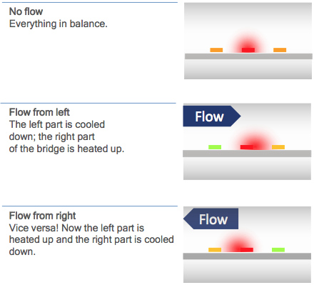
Thermabridge™ sensor technology responds to bidirectional flow.
Case 1. Two air compressor chambers
In a large electronic parts manufacturer, compressed air is used throughout the production process, including injection molding machines, product handling and packaging, parts pickup and placement, and metal parts plating and galvanizing. An energy management program has been initiated to reduce overall energy consumption at the plant. Compressed air is one of the utilities to watch. From an efficiency point of view, the factory air compressors are old. 10 years), there is room for improvement. In order to choose the right compressor, you need to measure the demand of the factory. But the company realized that permanent monitoring was the key to long-term cost savings. So instead of hiring an audit firm to perform an interim audit, they chose to implement a permanent compressed air flow monitoring solution - which could eventually be expanded to other utilities. The initial objectives of the first phase of the project are:
· Establish baseline data
· Select alternative air compressor combinations according to this profile
· Identify wastes and reduce air requirements in production areas
In the first phase of the project, we installed four compressed air flowmeters to get a clear picture of average demand. But after a few months, we came across an interesting situation where standard unidirectional compressed air flowmeters were producing useless results. In this particular case, backflow to the reservoir can lead to false readings, which can lead to serious measurement errors.
System description
The figure below shows a simplified layout of the compressed air system. The compressed air system consists of two compressor chambers (A and B). A network of compressed air rings is provided from these two separate compressor chambers. The compressor chamber is controlled by a pressure-based control system.
In compressor chamber B, two flowmeters are installed in a ring network to measure the air the compressor delivers to the network. Between the compressor and the network, a large receiving tank (5 m 3) is installed.
In Chamber A, three rotary screw air compressors are installed. These machines are used for daily base load. Each air compressor is equipped with the heat of a compressed drum dryer. Between the pipe and the compressor, two large receivers, each 5 m 3, were installed. From the receiver, two separate pipes supply compressed air to the production process.
One pipe is connected to another building where the compressor room B is located. The distance between the two compressor chambers is about 500 feet.
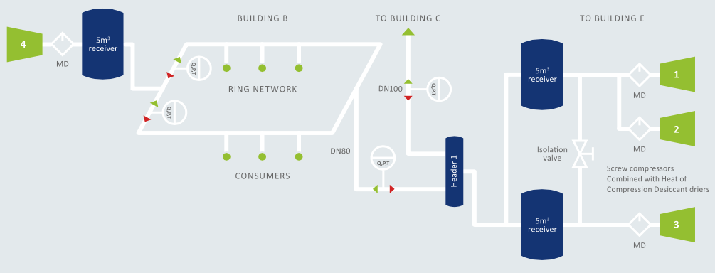
Figure 1 System overview - Click here to enlarge.
In compressor chamber B, there is a relatively new air-cooled ZT 145 machine. The air leaves the air compressor, goes into the heat of the compressed drum dryer, and then into another large air storage tank. Due to space constraints, it is not possible to install a single flowmeter between the outlet of the 5m 3 receiving tank and the network. Instead, the two flowmeters are installed further out in the ring network, behind the T-joint, where compressed air is fed into the ring. Initially, these standard VPFlowScope flowmeters are unidirectional. In other words: they won't see the difference between going forward and going backward. A few days later, strange measurements were observed. When the compressor is turned off, the flowmeter shows considerable measurements.
Countercurrent or not?
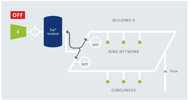
After carefully studying the configuration of compressor chamber B, we concluded that there must be counterflow when shutting down the air compressor. This effect is illustrated in detail in the figure below.
Shutdown of air compressor in room B: air storage tank behavior
During unloading and shutdown time, two unidirectional flowmeters show consumption, while one unidirectional flowmeter is expected to flow at zero. When local air demand in the ring network is low, the large reservoir will be filled by other compressors (from Chamber A), and when local demand is high, it will deliver air to the network. You can think of the receiver tank as a large balloon interacting with the network.
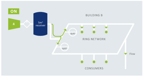
The air compressor in room B is in the state of "combined traffic"
When the compressor is operating at full capacity, compressed air is fed into the ring network. At T-junctions, the flow is combined with the existing "flow" depending on how the consumption of the roundabout is balanced. If air consumption is balanced, it may be perfectly symmetrical (50% left, 50% right), but when consumption is much higher on one side, the flow will be distributed differently. Pulsating demand can also change flow distribution for a short time.
Compressed air from the air compressor merges with air already flowing through the ring network. Depending on actual demand and eventual flow, this may result in high or low readings.
Shutdown of air compressor in room B: air storage tank behavior
The air compressor in room B is in the state of "combined traffic"
Unidirectional and bidirectional
Unidirectional compressed air flowmeters do not know where the air is coming from. This can lead to big errors. This applies to most thermal mass flowmeters based on thermal diffusion, thermostatic anemometry, etc. Other examples of one-way flowmeters include vortex flowmeters and turbine flowmeters, which are read by a standard pulse transmitter (the actual counter on the turbine flowmeter will rotate backwards). The venturi is also one-way. In reverse flow, the differential pressure signal will not turn negative. Orifice flowmeters can also measure countercurrent, but are not suitable for compressed air because of their permanent pressure loss.
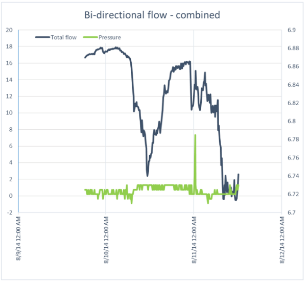
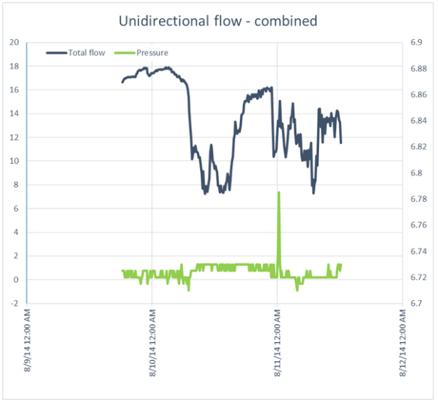
By enabling the bidirectional sensing function of VPFlowScope, the flow direction changes can be displayed in real time. The countercurrent is now shown as a negative value in the diagram. Let's look at some actual data: In the figure below, we have scaled up the measurements taken in compressor chamber B for a specific period of time. The raw data for the bidirectional flowmeters has been processed to show the differences between the bidirectional flowmeters. Directional and unidirectional flow.
At the end of this phase, the effect can be clearly seen: the compressor shuts down, and in the image on the left, the two bidirectional flowmeters cancel each other out, resulting in a flow rate of almost zero. On the right, the flow rate is not offset, resulting in a ghostlike signal approaching 13 m3 / min.
Is it unidirectional?
Some will say, why not link it to load/unload data for air compressors? When the compressor is unloaded or shut down, you know that the flow rate is zero, so you can compensate for it. We don't think this is the best way to address the counter-current problem because there may be other (real) causes of counter-current that are still not being noticed. For example, a leaky check valve, leaky seal or drain valve. In this particular case, we found a leak in the compressor seal. The annual cost of the leak is 1,314 euros, and it cost just 500 euros to fix. Another leak was found in the dryer. Again, this compressed air dryer leak is upstream of the flow meter, so it will not be noticed if the flow meter is one-way. The result is an annual leak cost saving of €2,102, while replacing hoses saves only €100.
- Previous article:On the field accuracy of flowmeter
- Next article:There is no more
For domestic enterprises of green energy conservation
Industry makes its own contribution
By searching on the website, you will receive the latest information on industry trends and developments, our products and solutions,
And information about our trade fair.